Fundamentals and Measurement Guide For Vector Network Analyzer
Vector network analyzer (VNA) is a measuring instrument which is primarily used to measure S parameters which determines RF (radio frequency) performance microwave devices. VNA is also called as a gain phase meter due to the fact that they are able to measure both the gain and phase of the device under test. They were also called Automatic Network Analyzer in the 1970s, even though the most popular term is VNA. Some vendors like Keysight prefer the term PNA, which can refer to Performance Network Analyzers.

Nowadays, it is getting popular among power electronic engineers too due to the high accuracy measurements required for control loop stability and impedance measurements. They can be used to characterize active and passive devices. Active devices include amplifiers, opamps, mixers, and tuners. Passive devices includes capacitors, inductors, ferrites and resistors. In general, they can be used to characterize a device with excellent accuracy since the measurements are band limited and the fixtures can be de-embedded. Generally, they are costly equipment even though cheaper versions like Omicron Bode 100 are available. Most common VNAs are two port devices, even though higher number of ports are available too. They are commonly used in signal integrity and power integrity measurements. Signal integrity measurements are required to characterize transmission lines accurately which in the end affect the signal quality. Even though the final quality of signal is measured in time domain using time domain reflectometer (TDR), the channel characterizations are performed or analysed better in frequency domain. This makes it necessary to have a VNA for signal integrity measurements.
VNA is an essential tool in power integrity measurements too. Characterizing a power supply and its associated power distribution network (PDN) is an important aspect of any processor power supply. The quality of the PDN and power supply affect the quality of signal too. So it is becoming extremely important to have a good flat PDN to avoid surprises. Multiple antiresonant peaks (parallel resonances) result in rogue waves which can generate voltages that are higher the individual responses at the antiresonant peaks. It is very important to suppress these antiresonant peaks to obtain a flat PDN response. The quality factor of antiresoances are suppressed by introducing losses into the system. High equivalent series resistance (ESR) capacitors are an option to reduce the antiresonant peaks. Final checking has to be performed with VNA. A characterisation with VNA makes sure that the impedance seen by a chip is flat to provide clean power to the chip. The characterization of PDN requires that the VNA is capable of making measurements in the range of micro ohms. Target impedance sets a target on the maximum impedance a flat PDN should have to provide. This is the ratio of maximum allowed voltage ripple to the maximum allowed current. Nowadays microohms of target impedances are common.
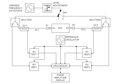
To accurately measure such low impedances a Vector Network Analyzer should be properly calibrated and the fixtures should be deembedded. De-embedding is the process by which we mathematically remove the impact of fixtures from the device under test (DUT). Very low impedances are accurately measured using 2-port shunt through measurements. Another common method of measuring impedance is by series measurements, even though they are suitable for impedances in the ohms range. 2-port shunt through impedance comes with an inherent ground loop, which is solved using either a coaxial transformer or a semi-floating amplifier.
To accurately measure such low impedances a Vector Network Analyzer should be properly calibrated and the fixtures should be deembedded. De-embedding is the process by which we mathematically remove the impact of fixtures from the device under test (DUT). Very low impedances are accurately measured using 2-port shunt through measurements. Another common method of measuring impedance is by series measurements, even though they are suitable for impedances in the ohms range. 2-port shunt through impedance comes with an inherent ground loop, which is solved using either a coaxial transformer or a semi-floating amplifier.


Comments
Post a Comment